User Tools
This is an old revision of the document!
Table of Contents
Milestone 3 Task 3: Complete the Laser Tag System
Overview
In this task you will complete the implementation of your laser-tag system and test it by connecting the transmitter output (generated by your transmitter state machine) to the Analog-to-Digital Converter (ADC) input. The connection between the transmitter pin (JF-1) and the ADC input are supplied via circuitry that is mounted on the development board to which the ZYBO board is mounted. Though you don't necessarily need to know all of the circuit details, a schematic of the related board circuitry is provided in the Resources Section below. Note: if you don't remember what an ADC is, you can review ADCs by consulting the concept on the web.
You will complete the system in this task by doing the following:
- Insert code that reads the output from the ADC and stores it as an integer. This code will be invoked in
isr_function()that is contained in isr.c. - Implement a buffer for storing values read from the ADC.
- Finish implementation of the detector. The detector refers collectively to all of the filtering code that you have tested and implemented thus far, plus some additional code that you will write and test in this task (see Organization of the Detector below).
- Demonstrate correct operation in continuous mode using the provided test code. In this mode, your system will continuously run the transmitter state machine at the frequency selected by the slide switches. The power is computed and displayed in histogram form. You can see a demonstration of continuous mode in this video. Note that newer boards may not have the potentiometer, but will work correctly; the new boards just lack the ability to attenuate the signal.
- Demonstrate correct operation in shooter mode using provided test code. In this scenario, you will press BTN0 to shoot. Shots are indicated and accumulated on the histogram screen. You can see a demonstration of shooter mode in this video.
- The shooter and continuous mode test functions are provided for you in runningModes.c. Calls to these functions can be enabled in main.c by uncommenting
#define RUNNING_MODE_M3_T3. Note that these files already exist in your project directory: ~/ecen390.
Organization of the Detector

Goal
The goal is to completely test your system sans guns, receiver boards and transmitter boards, and to completely verify that everything works correctly. When you connect your receiver and transmitter boards in Milestone 4, things should go pretty smoothly. If things don't work properly when you connect your boards and guns, you will know that the problem lies outside your software – you have already tested it completely. Thus you can focus on finding problems with your boards, cabling, etc. As you can guess, you would not want to debug your signal-processing software in conjunction with guns, receiver and transmitter boards, etc. That would be painful and frustrating, and a recipe for failure.
General Requirements
- Implement the code for the detector.
- Complete the functionality shown in the system organization diagram shown below (colored block diagram with the transmitter state machine controlled by the trigger state machine, etc.).
- You must demonstrate continuous mode with the provided software (runningModes.c). Your demonstration should be essentially the same as the demonstration video. Make certain that continuous mode works correctly before moving on to shooter mode.
- You must demonstrate shooter mode with the provided software (runningModes.c). Your demonstration should be essentially the same as the demonstration video.
- You must pass off using the provided main.c, and runningModes.c.
- Carefully follow all of the pass off requirements.
- Submit your code as follows. In the top-level directory, run
./check_and_zip.py 390m3-3 - You must follow the software coding standard. Exception: clang-format is not required. Ignore any clang-format rules.
Note: For this milestone and in the future, do not use interval timers in your code as these are used for computing run-time statistics for debugging purposes.
Resources
System Organization Diagram
The System Organization Diagram - Click the image for a larger view.
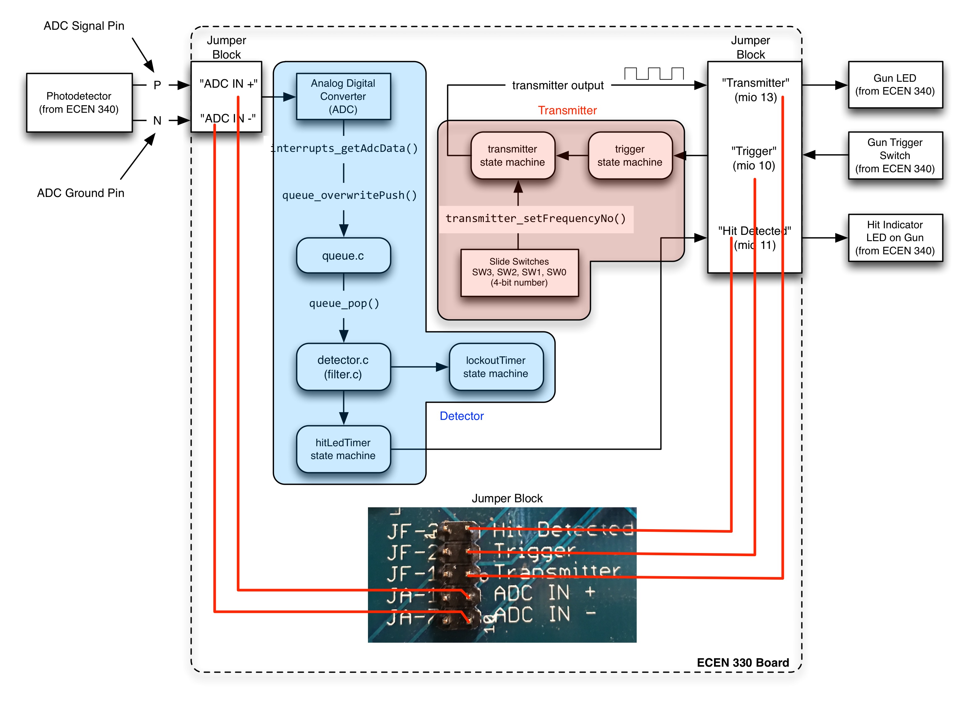
The loopback path (red lines) from the transmitter to the receiver is described in more detail on the loopback circuitry page. It is used for testing software without connecting a gun and other circuitry to the system.
Demonstration Videos and other Links
The links below provide demonstration videos for shooter and continuous mode, demonstrate how to change compiler optimization settings in the Xilinx SDK, and lead to sites that discuss different sort algorithms etc.
Source Code
Note that the following files are provided in your ecen390 project directory. Refer to the comments above each function for more details.
- include/interrupts.h
- lasertag/isr.h
- lasertag/buffer.h
- lasertag/detector.h
- lasertag/main.c
- support/bufferTest.h
- support/bufferTest.c
- support/runningModes.h
- support/runningModes.c
You are expected to create and implement the following files. See the provided header files (.h) for a description of each function.
- lasertag/buffer.c
- lasertag/detector.c
- lasertag/isr.c - continued from last task
Specifications
ADC Buffer
Implement a circular buffer in buffer.c that is dedicated to storing incoming integer data from the ADC. The code is similar to the code needed for queue.c. Why not just define a queue from queue.c and use that? You absolutely cannot under any circumstances use any floating-point data types (double or float) in any function that is invoked by an interrupt routine. The isr_function() is invoked by an interrupt routine, so when the ADC data is read and placed into a buffer, no floating-point types are allowed.
The solution is to create a circular buffer that stores integers of type uint32_t. Implement a set of functions as follows:
buffer_init(): this initializes the ADC buffer much likequeue_init()does. It would make sense to haveisr_init()invoke this function.buffer_pushover(uint32_t value): this is similar toqueue_overwritePush()with an uint32_t argument instead of a double. If the circular buffer is full, overwrite the oldest value.buffer_pop(): this is similar toqueue_pop()that returns a uint32_t instead of a double.buffer_elements(): this is similar toqueue_elementCount().buffer_size(): simply returns the capacity of the buffer in elements.
Note: you will have to write most of this ADC buffer code. See ADC Buffer Sketch below for code to get started. You can also refer to your queue.c code for inspiration (but don't copy any double data types if you cut and paste).
Carefully test your ADC buffer code independent of the detector. You can do this by uncommenting buffer_runTest() in main.c. It will not be possible to fully test your detector implementation if the buffer is not working properly.
Interrupt Service Routine
Continue the implementation of isr.c
isr_init():- Perform initialization for timing related modules (those with
tick()functions). - Add a call to
buffer_init().
isr_function():- Invoke all of the tick functions.
- Grab data from the ADC and store it in the ADC buffer at the rate of 100 kHz.
Getting ADC Data
Use the function: uint32_t interrupts_getAdcData(). It is declared inside interrupts.h. When invoked, it returns the current value from the ADC. The ADC is programmed to run continuously. As such, you are just grabbing the most recent value from the ADC. Once you get the value, put it into the ADC buffer using buffer_pushover(). This task must be performed at the 100 kHz rate so place this code inside isr_function().
The Complete Detector
When you invoke detector(), perform the following steps.
- Query the ADC buffer to determine how many elements it contains. Use
buffer_elements()for this. Call this amountelementCount. - Now, repeat the following steps
elementCounttimes.- If interrupts are enabled (check to see if the interruptsEnabled argument == true), briefly disable interrupts by invoking
interrupts_disableArmInts(). You must disable interrupts briefly while you pop an element from the ADC buffer. Otherwise, if an interrupt occurs while you are “popping” a value from the buffer, the interrupt routine and yourdetector()routine may simultaneously access the ADC buffer and may causeindexIn,indexOut, or some other field of the ADC buffer to be miscomputed. This kind of problem can be very difficult to track down because it is hard to reproduce, so it is best to avoid the problem in the first place. - Pop a value from the ADC buffer (use
buffer_pop()for this). Place this value in a variable calledrawAdcValue. - If the interruptsEnabled argument was true, re-enable interrupts by invoking
interrupts_enableArmInts(). - Scale the integer value contained in
rawAdcValueto adoublethat is between -1.0 and 1.0. Store this value into a variable namedscaledAdcValue. The ADC generates a 12-bit output that ranges from 0 to 4095. 0 would map to -1.0. 4095 maps to 1.0. Values in between 0 and 4095 map linearly to values between -1.0 and 1.0. Note: this is a common source of bugs. Carefully test the code that does this mapping. - Invoke
filter_addNewInput(scaledAdcValue). This provides a new input to the FIR filter. - If filter_addNewInput() has been called 10 times since the last invocation of the FIR and IIR filters, run the FIR filter, IIR filter and power computation for all 10 channels. Remember to only invoke these filters and power computations after
filter_addNewInput()has been called 10 times (decimation). If you have just run the filters and computed power, also do the following:- if the lockoutTimer is not running, run the hit-detection algorithm. If you detect a hit and the frequency with maximum power is not an ignored frequency, do the following:
- start the lockoutTimer.
- start the hitLedTimer.
- increment detector_hitArray at the index of the frequency of the IIR-filter output where you detected the hit. Note that detector_hitArray is a 10-element integer array that simply holds the current number of hits, for each frequency, that have occurred to this point.
- set detector_hitDetectedFlag to true.
You will implement the detector in detector.c. The header file detector.h is already provided with the laser tag project. Here is an overview of the required functions.
detector_init(): Initializes the detector module. By default, all frequencies are considered for hits. The function assumes the filter module is initialized previously.detector_setIgnoredFrequencies(bool freqArray[]): You pass it a preinitialized array of 10 booleans. If freqArray[0] is true, for example, no hits should be registered for this frequency when you run the detector() function.detector(bool interruptsCurrentlyEnabled): This runs the entire detector once each time 10 new inputs have been received, including the decimating FIR-filter, all 10 IIR-filters, power computation, and the previously-described hit-detection algorithm.detector()sets a boolean flag to true if a hit was detected. The interruptsCurrentlyEnabled flag will be set to true if interrupts are enabled and false otherwise.detector_hitDetected(): Simply returns the boolean flag that was set bydetector(). Example code provided in runningModes.c callsdetector()and then callsdetector_hitDetected()to determine if you have been hit.detector_clear(): This function simply clears the aforementioned flag.detector_getHitCounts(): This function simply copies the values from the detector_hitArray into the supplied argument. You provide an array of size 10 as the only argument. After invoking this function, the array will contain the same values as detector_hitArray.detector_runTest(): When invoked, this function will test the functionality of your detector software. This test function is described below.
Implementation Details
ADC Buffer Sketch
A sketch is given below as a starting point for an implementation of buffer.c. You will need to finish the implementation.
- buffer.c
#include "buffer.h"

// This implements a dedicated circular buffer for storing values
// from the ADC until they are read and processed by the detector.
// The function of the buffer is similar to a queue or FIFO.

// Uncomment for debug prints
// #define DEBUG

#if defined(DEBUG)
#include <stdio.h>
#include "xil_printf.h" // outbyte
#define DPRINTF(...) printf(__VA_ARGS__)
#else
#define DPRINTF(...)
#endif

#define BUFFER_SIZE 32768

typedef struct {
    uint32_t indexIn; // Points to the next open slot.
    uint32_t indexOut; // Points to the next element to be removed.
    uint32_t elementCount; // Number of elements in the buffer.
    buffer_data_t data[BUFFER_SIZE]; // Values are stored here.
} buffer_t;

volatile static buffer_t buf;


// Initialize the buffer to empty.
void buffer_init(void)
{
}

// Add a value to the buffer. Overwrite the oldest value if full.
void buffer_pushover(buffer_data_t value)
{
}

// Remove a value from the buffer. Return zero if empty.
buffer_data_t buffer_pop(void)
{
}

// Return the number of elements in the buffer.
uint32_t buffer_elements(void)
{
}

// Return the capacity of the buffer in elements.
uint32_t buffer_size(void)
{
}
Detecting "Hits"
Now that you have completed the previous milestones, you have code that can compute the total power that passes through each of your IIR-based bandpass filters. Now what? Here are some considerations.
- You could always select the band-pass filter output that contains the maximum power relative to the others. Unfortunately this simple scheme won't work because it would always detect a “hit” of some sort, even when no one is shooting at you. Due to various noise sources, there will always be some power in at least some of the frequencies, even when no one is shooting at you.
- You could select the frequency that contains a power value that is above some threshold. This “kind of” works; however, it is difficult or impossible to come up with a threshold that works in enough situations. For example, let's say you perform some experiments in indoor light with the two guns spaced apart by about 10 feet. In continuous mode, you can see the power values that are being captured and so you set the threshold so that “hits” are only detected when the computed power is above the threshold. OK so far. Now you move the guns so that they are 20-feet apart. Now, when you press the trigger, nothing happens because the power numbers across all frequencies are not above the threshold. You can lower the threshold to increase sensitivity and detect “hits” at greater distances. However, at some point you will begin to detect noise (from your amplifier circuitry, from the ambient lighting, etc.) as a “hit”. Clearly, just comparing the power in the band-pass filter outputs to a fixed threshold won't work very well.
A Hit-Detection Algorithm
We will use an algorithm that adjusts the threshold based upon the current power contained in the outputs from all 10 band-pass filters.
The detection algorithm consists of the following steps:
- After running all of the filters and computing the power for each band-pass filter output, sort the power values in ascending order according to their magnitude. Just use an insertion sort or a selection sort algorithm to do the sorting. Here is a very simple insertion-sort tutorial based on playing cards. Pro Tip: sort a separate array containing the indices of the original array.
- Select the median value. Selecting the median value is simple once you have sorted the power values – the median value is simply the value “in the middle” of the set of sorted values. For our system, we have 10 power values; once they are sorted in ascending order, the median value is either the 5th or 6th element according to the sorted order. Everyone should sort values in ascending order and select the 5th value for consistency.
- Multiply the median value with a “fudge-factor” to compute a threshold. This computed threshold should be high enough to reject noise and avoid false “hits” but should be low enough to detect hits from a distance of 40 feet or so. You will compute the fudge-factor through experimentation. Why use a fudge-factor? The fudge-factor makes it possible to accommodate the different characteristics for everyone's analog board. For this task, the fudge factor can be pretty high, say 1000 or so. Once you connect the guns in the next task, you will need to lower the fudge factor to maximize your range.
- Find the band-pass filter that contains the maximum power (this is easy to do once you have sorted the values). If the maximum power exceeds the threshold (median-value * fudge-factor), you have detected a hit.
Hit-Detection Algorithm Example
Here is an example of the hit-detection algorithm in operation. Assume the fudge-factor = 5. Let's say that we retrieve the current power values for all 10 frequencies using the previously-implemented function: filter_getCurrentPowerValue(uint16_t filterNumber). The retrieved power values for the 10 frequencies for this example are:
- power[0]: 150
- power[1]: 20
- power[2]: 40
- power[3]: 10
- power[4]: 15
- power[5]: 30
- power[6]: 35
- power[7]: 15
- power[8]: 25
- power[9]: 80
After sorting in ascending order, we get the following:
- power[3]: 10 (#1)
- power[7]: 15 (#2)
- power[4]: 15 (#3)
- power[1]: 20 (#4)
- power[8]: 25 (#5)
- power[5]: 30 (#6)
- power[6]: 35 (#7)
- power[2]: 40 (#8)
- power[9]: 80 (#9)
- power[0]: 150 (#10)
The median value (sorted element #5) is 25 from the band-pass filter for frequency 8. For this example set of data that would mean that you would only detect hits for values that are over the threshold value of 25 (median value) * 5 (fudge-factor) = 125. The band-pass filter for frequency 0 has the maximum power value (150) which is greater than 125 so we would detect a hit.
Let's run the detector again with another set of data. After sorting, the power values from the band-pass filter outputs are as follows:
- power[2]: 10 (#1)
- power[1]: 25 (#2)
- power[4]: 30 (#3)
- power[7]: 30 (#4)
- power[8]: 45 (#5)
- power[6]: 50 (#6)
- power[5]: 55 (#7)
- power[3]: 65 (#8)
- power[9]: 70 (#9)
- power[0]: 150 (#10)
Our median value (element #5 in sorted order) = 45. We compute the new threshold by multiplying 45 * 5 (fudge-factor) = 225. Our maximum power value (150) is less than our computed threshold (225) so no hit is detected. The reason no hit is detected is because the maximum power is not sufficiently greater than the power contained in the outputs of the other band-pass filters.
Note that these numbers are provided solely for example. The actual numbers you will encounter in your system will be quite different.
Determining the Fudge-Factor
A wide range of fudge-factor values will work when using the loop-back circuitry on the board for this task. I have successfully tested systems with fudge factors as high as 10,000. However, such high values won't work when you attach the guns. For this task, you can probably just select a value between 200 and 1,000. If you note false detections during shooter mode, raise the fudge-factor until they are eliminated.
The general idea behind this detection approach is that the threshold tracks the current background noise to some degree. Thus if the frequency channels all have power values that are a little high, the computed threshold also tracks higher. Vice versa, if the frequency channels all have power values that are lower, the computed threshold also tracks lower. In practice this detection strategy has worked quite well, often achieving distances of 100' in daylight.
You will implement this hit-detection algorithm in this task.
Pass Off
To pass off your system to the TAs, you must do the following:
- Demonstrate an isolated test of your detector (see instructions for the isolated test below).
- Demonstrate a system test of the entire laser-tag system as implemented thus far (see instructions below regarding shooter and continuous modes).
- Run ”./check_and_zip.py 390m3-3” to create a .zip file of your project. Submit only one .zip file per team. The TAs will give credit to both members of the team.
1. Detector Isolated Test
You will write detector_runTest() and demonstrate its operation to the TAs.
detector_runTest() will test your hit detection algorithm using the isolated test described below. As a suggestion, organize your hit detection algorithm into a local sub function named hit_detect() so it can be called by the test. This sub function would also be called by detector().
Isolated Test Details
For this test, simply provide power data for your hit detect function by calling filter_setCurrentPowerValue() for each of the 10 frequencies. Then call your hit detect function, which should retrieve the power values. The isolated test must perform the test upon two sets of data as described below:
- Create a first set of power data (10 calls to
filter_setCurrentPowerValue()) and provide a fudge-factor value that will detect a hit when you invokehit_detect(). After callinghit_detect(), you would invokedetector_hitDetected()to determine if a hit occurred. - Create a second set of power data that will not detect a hit when you invoke
hit_detect(). Use the same fudge-factor as you used for the first set of data. Again, invokedetector_hitDetected()to determine if a hit occurred.
2. System Demonstration
Enable the shooter and continuous mode test functions provided in main.c. Demonstrate your system in both shooter and continuous mode and show that your system runs the same as the videos:
While in continuous mode, allow the graphical display to settle for at least 10 seconds (by not switching frequencies) and then press and hold BTN3 until the program exits and displays the run-time performance values. Similarly, for shooter mode, don't shoot for about 10 seconds before pressing BTN3, again, so the graphics will settle and so that the performance values are more accurate.
Show the performance values to the TAs. In general, these run-time values should be reasonable:
- Your ADC queue should never be full. On average you should see a low number. An occasional number in the low hundreds may be OK as the histogram display takes awhile to complete.
- Run-time in timerIsr should be 10-20% or less.
Note that the performance values shown below are “ballpark” figures. Don't worry too much if your statistics vary a fair amount from those shown below.
The picture shown below is for shooter mode.

The picture shown below is for continuous mode.

Notes to the TAs
TAs: please pay attention to the following during pass off and when you are grading source code.
- Verify that the run-time statistics that are printed out when the program exits are in the ball-park. Cumulative time spent in timer ISR should be around 10% - 25%, but allow the pass off if the code properly demonstrates shooter mode and continuous mode.
- In shooter mode, verify that shots accumulate correctly and that the system responds quickly to a press of BTN0. Try all frequencies.
- In continuous mode, check for reasonable power values. Try all frequencies.
- All of the test functions must be passed off as described above in order to pass off.
- No compiler warning or errors when compiling student code.
